Manual Technician
This manual is intended for the technician who will build, install and prepare SUIT, systems COLT-02 and HK-01 for training. This guide describes the following topics:
Location scouting
Overview of the minimum requirements that a location must meet in order to train with SUIT, system COLT-02 and HK-01.
Instructions for performing a positioning test to check the location for any malfunctions.
Setting up the system
Construction scheme and sequence for assembling the system and instructions for assembling per SUIT part.
Maintenance tab
Explanation about switching parts on and off in the maintenance tab of SUIT when deploying a spare.
Map scanning the training field
Instructions for measuring the training field and for reading the data on the EXCON.
System shutdown
Instructions for shutting down the system.
Leaving the system unattended
Instructions for shutting down and partially storing the system when left unattended for a while.
Taking down the system
Sequence for taking down the system and a manual for the taking the system down per SUIT part.
Maintenance
Description for maintaining the different parts of SUIT.
Location Scouting
Read the safety rules carefully before scouting. This sets out minimum requirements that must be met before the location can be assessed.
Before the SUIT training can take place at a certain location, it must be checked whether this location is suitable for training with SUIT, system COLT-02 and HK-01. Firstly, a location must meet a number of minimum requirements. If the location meets all minimum requirements, a location test with the system must be performed. This requires a minimum of two people.
Minimum location requirements
Before setting up the system, check whether the room meets the minimum requirements for training with SUIT:

Room
Minimum 32.5 x 32.5 meters obstacle-free space
So there is enough space for a training field of 30 x 30 meters – the dimensions of the largest scenario – with enough space all around to be able to walk around the training field. This space must be free of obstacles, such as pillars.
At least 32.5 x 4 meters of space next to the training field
For setting up the EXCON, spectator, Smartvest hanging racks and replica charging case. Determine in advance where these parts will be placed. Allow for sufficient freedom of movement around the spectator and the coat racks.

Floor
Level floor
The floor must be flat, without differences in height or unevenness.
Clean
The floor must be free of dust or sand. If necessary, arrange a sweeper or broom service for this.

Ceiling height
At least 2.5 meters high
At this ceiling height there is enough space for the tripods with the Access Points.

Temperature and humidity
Temperature between 15°C and 35°C
The temperature in the room must remain between these limits during use. Even when the system is left unattended, the temperature must remain within these values to prevent damage to the equipment.
Humidity between 20% and 90%
Only use the system at a relative humidity between 20% and 90% (no condensation).

Room
Lighting
The room must be sufficiently lit and as little natural light as possible for optimal tracking.
Table and chair
A table with chair must be available for operating the EXCON.

Power supply
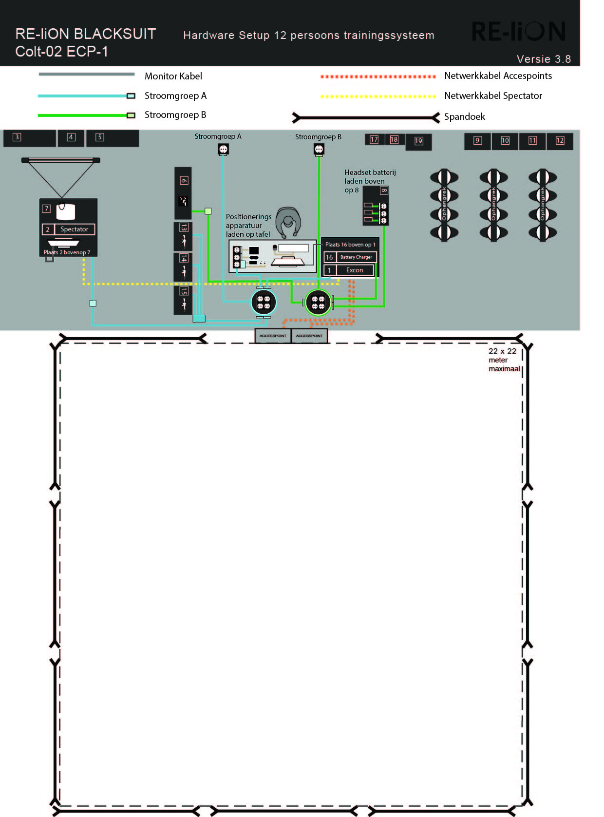
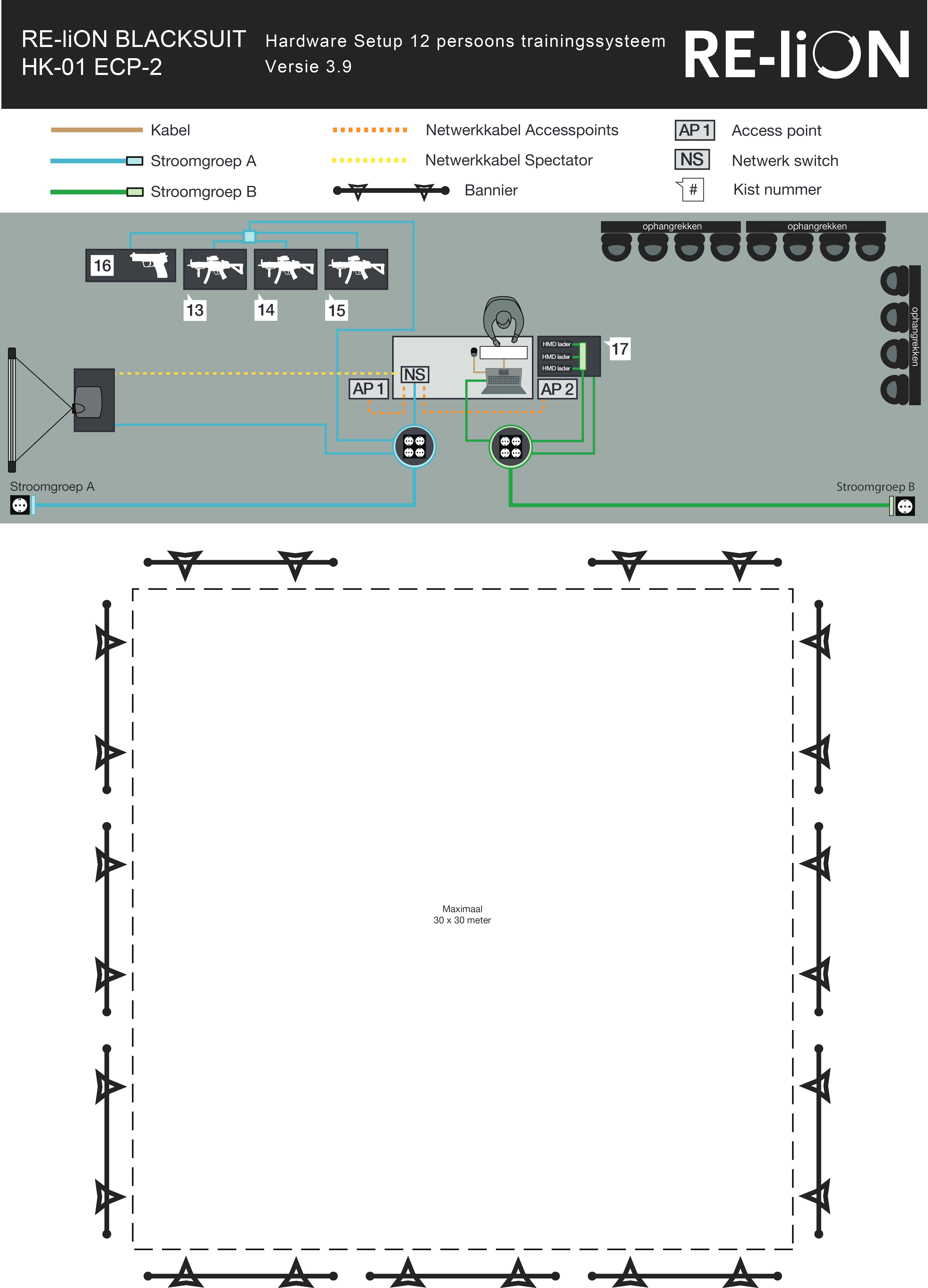
Always follow the connection diagram for connecting all the equipment of the RED-01 system.
Maximum power: 3605 W divided into three groups:
- Power group A: 1887W (Maximum current: 8.2 A)
- Replica cases
- Case 2 SPECTATOR
- Power group B: 1468W (Maximum current: 6.4 A)
- EXCON laptop
- HMD battery chargers
- Battery charger
- Optional Power Group: 250 W (Maximum current: 1.1 A)
- Case 12 SUIT DEVELOPMENT STATION (using the BS 1363 cable)

Channels
At least 1 unused, interference-free, non-overlapping and 40 Mhz wide radio channels in the 5Ghz WiFi band
Check which channels are in use via Wifi Analyzer.
CAUTION
If there are chairs or benches that contain metal, people wearing a Smartvest are NOT allowed to sit on them. The presence of these objects in the room does not hinder training with SUIT.
WiFi Analyzer Mobile
The WiFi Analyzer Android app shows which WiFi channels are in use. Use the app as follows:
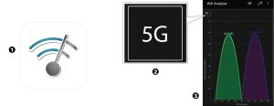
Download the Wifi Analyzer app on the smartphone from the Google Play Store and open the app.
Tap once with your finger on the first screen so that the type of network appears in the top left of the screen. If it’s set to 2.4G, tap it to set the network to 5G.
Check that the WiFi paths/channels of the suit WiFi do not cross each other and check that there are no other WiFi channels through the suit WiFi. The image below shows the ideal situation.
WiFi Analyzer SDS Laptop
The WiFi Analyzer Android app shows which WiFi channels are in use. Use the app as follows:
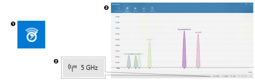
Open the Windows menu using the Windows key and search for Wifi analyzer. Then open the program by clicking on it. Then click on the Analysis tab in the program.
Check whether the 5GHz is on at the bottom right of the program. If it’s set to 2.4G, tap it to set the network to 5G.
Check that the WiFi paths/channels of the suit WiFi do not cross each other and check that there are no other WiFi channels through the suit WiFi. The image below shows the ideal situation.
Setting up the system
Preparation
- Before you start setting up, place all the cases in the right place in the room – but not yet on top of each other – according to the setup diagram below.
- Check if all cases are complete using the inventory list.
- Check all cables and connectors for damage. Arrange the cables in orderly paths as much as possible and make sure that there are no loops and kinks in the cables.
Setting up
When setting up SUIT, keep the following in mind:
Order of setting up
Make sure that the EXCON is always set up first and dismantled last. All documentation is located on the EXCON. In addition, the position of the EXCON determines the position of the training field.
Cable reels with residual current circuit breaker (RCCB)
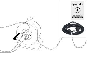
- Make sure that the cable reels are completely unwound.
- Only use the cable reels on grounded sockets.
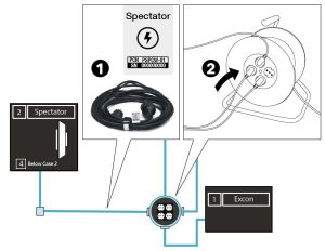
- Connect the two cable reels each to their own grounded socket with power group. The cable reels may not be connected via each other – daisy chain.
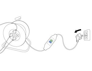
- The cable reels are equipped with an residual current circuit breaker (RCCB) “EPP Elimit” with a green RESET button and a blue TEST button. Whenever a reel is connected to the mains, the following instructions must be followed (these instructions are also printed on the back of the RCD)
How do you use the Elimit?
- Place the plug of your Elimit in a wall socket.
- Press the RESET button to activate your Elimit. The indicator changes from black (off) to red (on).
- Remove the plug from the wall socket. The Elimit turns off (the indicator changes to black).
- Repeat point 1 and 2.
- Press the TEST button. Your Elimit will turn off again (the indicator will change to black).
- Press the RESET button to reactivate your Elimit (red).
- Connect your appliance or power tool to your Elimit and you can get to work safely.
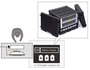
- Make sure the correct devices are connected to the correct reel. The battery charger must be connected to its own power group, without other devices. The EXCON, spectator and replicas must be connected to the other power group.
Cooling
- Keep a minimum of 30 cm clearance around the EXCON, battery charger and spectator for cooling.
- Leave the gear charge case open for cooling while the gear is charging.
Setting up the EXCON
Necessities
CASE 01 | EXCON
CASE 05 | Positioning B
-> Cable reels with residual current circuit breaker
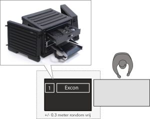
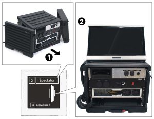
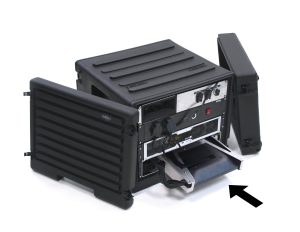
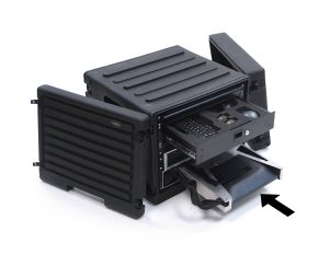
Place the EXCON next to the table on the floor and make sure that there is at least 30 cm of space around it for cooling. Remove the lids. The front – the side with the drawers – faces the operator. The back – the side with the cable connections – points towards the training field.
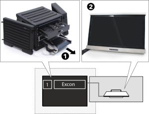
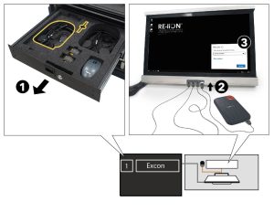
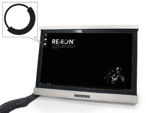
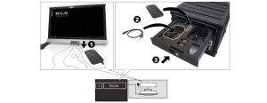
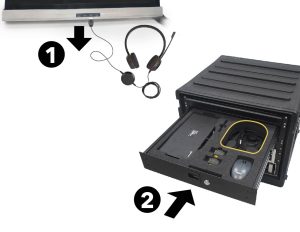
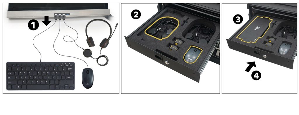
Remove the monitor from the bottom drawer of the EXCON (1) and place it on the table (2).
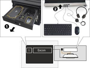
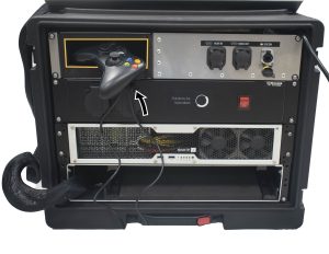
Take the keyboard, mouse and one of the two headsets from the top drawer of the EXCON (1). Connect the keyboard, mouse and headset to the USB ports under the monitor (2). The other headset will be needed later at Placing Spectator.
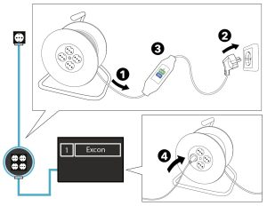
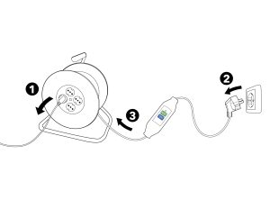
Completely unwind the cable reel (1), insert the plug into the socket (2) and follow the instructions on the back of the residual current circuit breaker (RCCB) (3). Place the cable reel next to the EXCON and connect the EXCON mains cable to the cable reel (4).
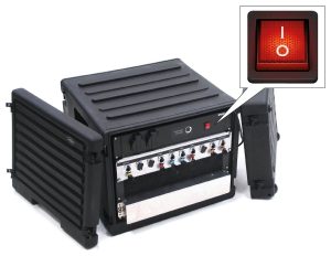
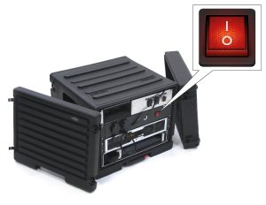
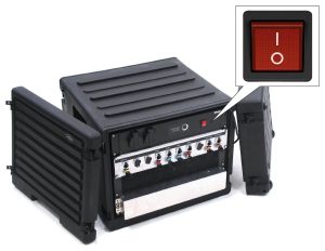
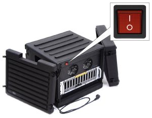
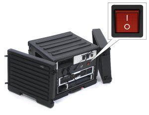
Press the red ON/OFF switch on the back of the EXCON on I.
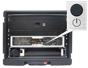
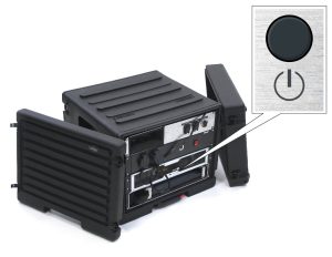
Press the ON/OFF button on the front of the EXCON to start up the computer and wait for it to boot up completely.
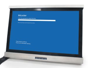
Enter the password on the computer and press enter to prevent the system from shutting down again.
Take the external hard disk and the associated USB cable from the top drawer of the EXCON (1) and connect the hard disk with the USB cable to the USB port under the monitor (2). Enter the password and click Unlock to start SUIT.
Double click on the SUIT icon to start SUIT.
Setting up Smartvests
Necessities
Depending on number of players
CASE | 03 Smartvest hanging racks
CASE | 06 Smartvests
CASE | 07 Smartvests
CASE | 08 Smartvests
CASE | 09 Smartvests
CASE | 10 Smartvests
CASE | 11 Smartvests
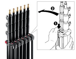
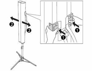
Take the tripods for the hanging racks out of the box and click them apart by pressing the red button (1)(2).
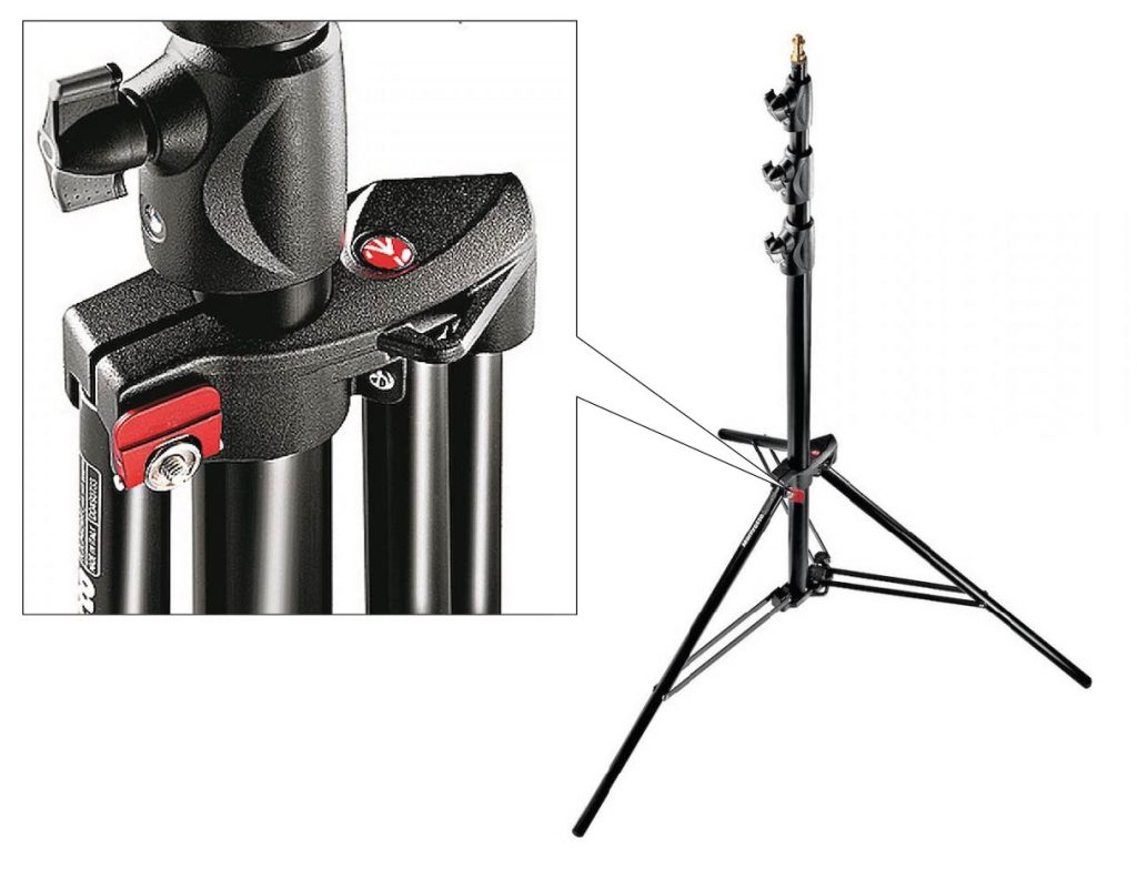
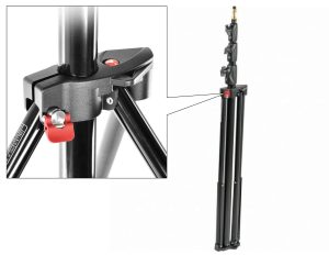
Loosen the red locking screw and unfold the three legs. Then retighten the locking screw.
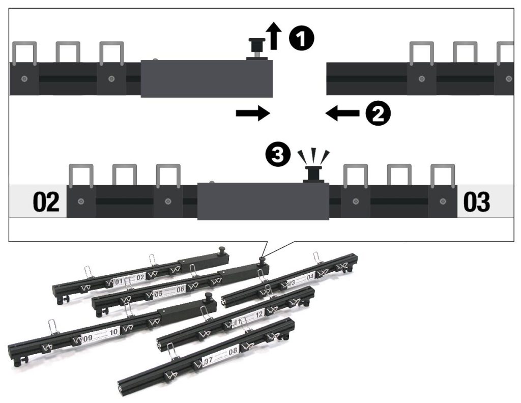
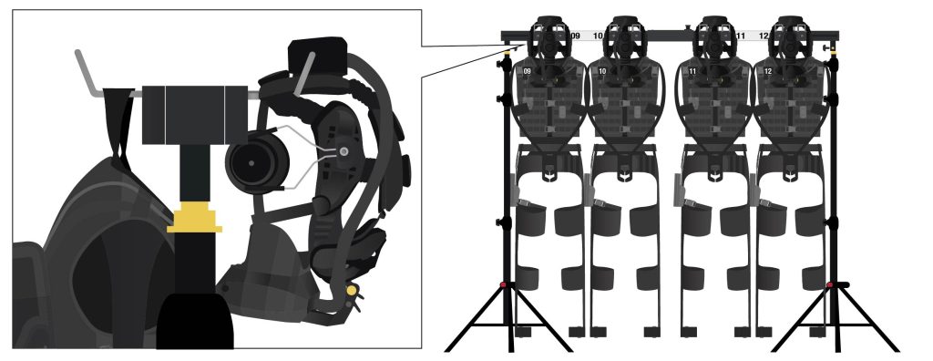
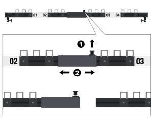
Slide the hanging racks together with hooks. Pull the locking knob up (1) and slide two parts together (2) until the locking knob clicks into place (3). Combine suspension racks 01/02 with 03/04, 05/06 with 07/08 and 09/10 with 11/12.
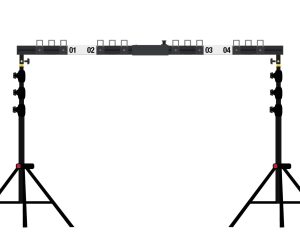
Place the hanging rack on a tripod on both sides and secure it with the wing bolts.
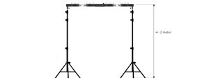
Set both tripods at the same height (about 2 meters: not too high in connection with lifting above shoulder level, but high enough so that the suits do not hang on the floor). When adjusting the height, slide the thickest extension of the tripod up as far as possible for the best stability.
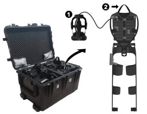
Open the boxes with Smartvests. First take the headset (1), and then the Smartvest (2), from the box. Wear the Smartvest on the suspension loop on the back.
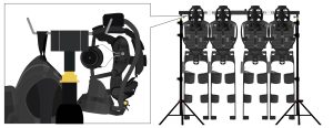
Hang the Smartvest, on the hanging loop, on the single hook on the back of the hanging rack and hang the headset, on the headband, on the double hooks on the front of the hanging rack.
PAY ATTENTION
Make sure that:
– all cables hang freely.
– the three buckles on the front of the vest are closed.
– all Velcro parts are closed.
– the legs hang down neatly apart from each other.
– the forearms at the front of the Smartvest are connected to each other with the Velcro of the forearm sensor.
Setting up replicas and chargers
Necessities
CASE 05 | Positioning B
-> Cable reels with residual current circuit breaker
-> Power cable gear charging case
CASE 12 | Replica Glock
CASE 13 | Replica
CASE 14 | Replica
CASE 15 | Replica
CASE 16 | Battery charger
WARNING
Gear and batteries should not be charged for more than a continuous period of 16 hours. After this time at the latest, disconnect the gear charging box and battery charger from the electrical outlets. Adequate measures must be taken to ensure that the temperature in the room in which charging takes place cannot rise.
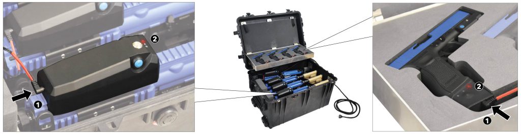
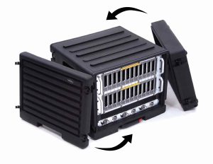
Place the battery charger on the other side of the table with the EXCON and make sure that there is at least 30 cm of space around it for cooling. Remove the lids.
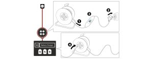
Completely unwind the cable reel (1), insert the plug into the socket (2) and follow the instructions on the back of the residual current circuit breaker (RCCB) (3). Place the cable reel next to the battery charger and connect the battery charger mains cable to the cable reel (4).
PAY ATTENTION
The battery charger must be connected to its own power group, with no other connected devices. Connect the battery charger cable reel to a grounded outlet with its own power group.

Press the red ON/OFF switch on the back of the battery charger to I.
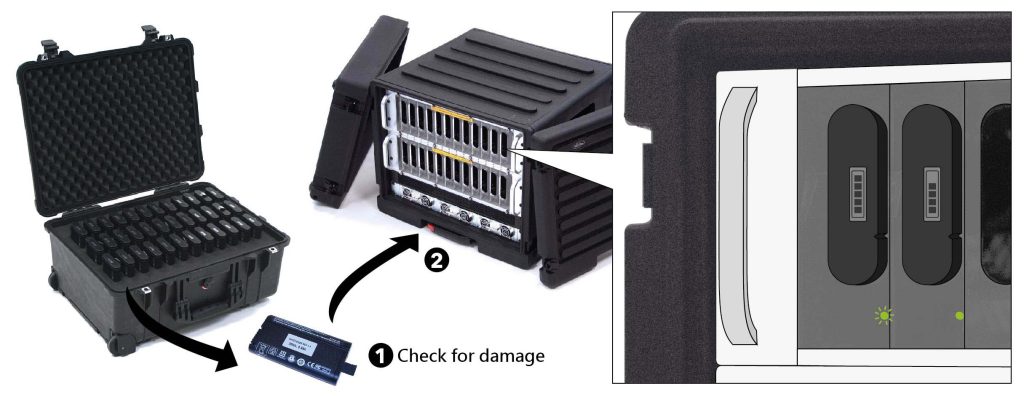
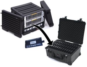
Remove the batteries from the battery transport box and check them for damage (1). Place them – only if they are not damaged – in the chargers of the battery charger (2). The battery is charging when the green LED at the bottom right of the battery starts flashing. The battery is fully charged when the green LED remains lit.
WARNING
When batteries have been dropped or damaged, this must always be reported to the supplier RE-liON. These batteries should NOT be used anymore.
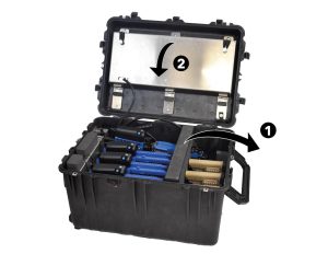
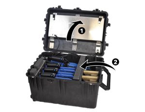
Open the replica chest. First remove the insert from the box (1) and then open the steel drawer in the lid (2).
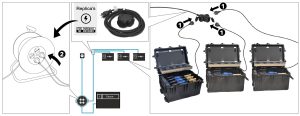
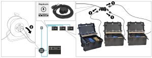
Connect the mains power cables from the replica boxes to the mains power cables replicas (1). Connect the mains voltage cable replicas to the cable reel next to the EXCON (2).
PAY ATTENTION
Beware of tripping. Arrange the cables in orderly paths as much as possible and make sure that there are no loops or kinks in the cables. Tape the cables to the floor with duct tape if necessary.
Connect all replicas to the charging cables. The replicas are charging when the right LED of the three LEDs turns red.
PAY ATTENTION
When the charging light is no longer lit, the replica is fully charged.
Setting up the training field
Necessities
CASE 04 | Positioning system A
CASE 05 | Positioning system B
-> 8 tripods
CASE 06 | Cables
-> 2 network cables type A
-> 2 network cables type B
-> 4 network cables type C
-> 2 network cables access point
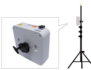
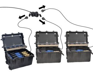
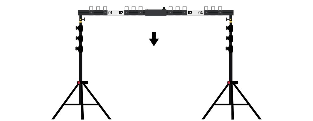
Take both access point modules out of the box and slide an access point module onto two tripods. Place the modules right side up – with stickers marked on the access point module – and secure them with the wing bolt. Then connect the network cable to the EXCON.

Check that the access points are working properly. Insert batteries in Smartvest 1 and 12 and turn on both Smartvests by pressing the ON/OFF button on the backpack box (see Smartvests). In SUIT, go to Start training → 2. Physical Gear → Smartvests tab and check the list to see if Smartvest 1 and 12 come online. If the status is Rotary knob they are fully online.
If necessary, perform a comprehensive check by turning on all smartvests and checking to see if they all get Rotary knob status.
PAY ATTENTION
If the Smartvests are not going to be used immediately after setup, turn the Smartvests off after the check by holding down the ON/OFF button on the Smartvest until the display indicates Shutting Down. WAIT FOR THE MESSAGE SYSTEM OFF! Remove the batteries from the smartvests and insert them back into the battery charger. The battery is charged when the green LED on the top left of the battery starts flashing.
PAY ATTENTION
Beware of tripping. Cables should run completely across the ground around the training field and should only go up through the base of the tripod toward the radio receiver. Lay the cables together in orderly courses as much as possible and make sure there are no loops or kinks in the cables. If necessary, tape the cables to the ground with duct tape.
Setting up the Spectator
Necessities
CASE 02 | Spectator
CASE 05 | Positioning system B
-> Spectator projection screen
-> Power cable Spectator
-> Network cable Spectator
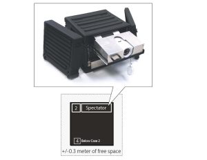
Place the spectator on an empty box 4 (positioning system A) and ensure that there is at least 30 cm of space around it for cooling. Remove the lids.
Remove the monitor from the bottom drawer of the Spectator (1) and place it on the box (2).
Connect the mains voltage cable that is attached to the spectator to the power cable extension spectator (1). Then connect the extension cord to the cable reel next to the EXCON (2).
Press the red ON/OFF switch on the back of the Spectator to I.
Press the ON/OFF button on the back of the Spectator to start up the computer.
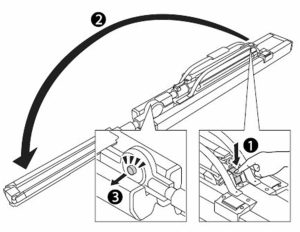
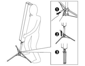
Place the Spectator projector screen on the floor and press the button (1) to unfold the tripod (2) until it clicks into place in the final position (3).
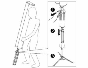
Press the button under the screen (1) and slide the legs out (2) until they click into the final position (3).
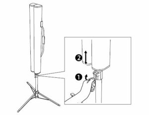
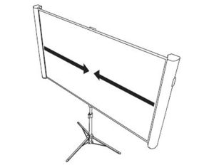
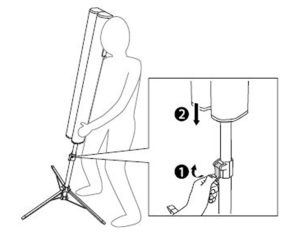
Push the adjusting clamp up (1), slide the projection screen to the desired height (2) and fasten again by pushing the adjusting clamp down.
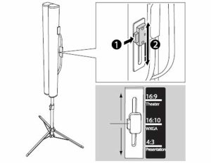
Adjust the projection screen to the desired screen ratio (1)(2).
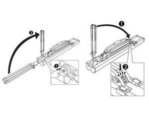
Open the projection screen by pressing both buttons simultaneously (1) and slide the projection screen completely open (2).
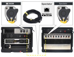
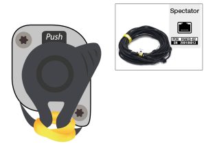
Connect the network cable Spectator between the Spectator and the EXCON. The spectator cable is marked yellow. Only connect the connectors to a yellow marked terminal. Remove the protective cap from the connection point and connect the connector.
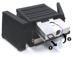
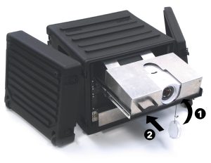
Slide out the projector of the Spectator (1) and remove the protective cap from the lens (2).
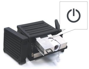
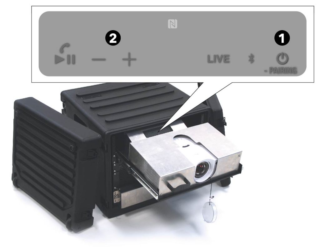
Press the ON/OFF button on the top of the projector to start up the projector.

Focus the image with the adjustment ring near the lens.
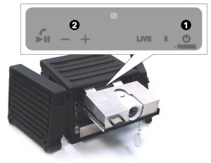
Press the ON/OFF button behind the projector to switch on the speakers (1) and adjust the volume of the sound with the + and – buttons (2).
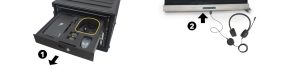
Connect the extra headset (included in the EXCON box (1)) to the USB connection on the screen of the Spectator (2).
PAY ATTENTION
After setting up, place all unused cases in a place where the participants will not be affected.
Maintenance tab
Maintenance tab
In the maintenance tab, parts of the system can be enabled or disabled. Enabled items in the maintenance tab are recognized by the system the moment they are turned on.
In addition, the maintenance tab allows you to set the system language and laser color for all weapons.
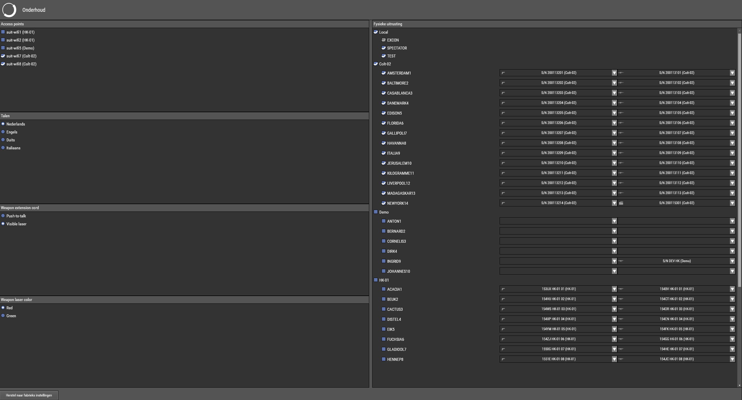
Access points
All access points are listed here. The ones belonging to the system in use need to be selected
Languages
The language of the system can be set under this tab. The language is set to Dutch by default. When the language is changed, the SUIT server must be restarted. Click in SUIT and in the RE-liON SUIT Server Log Window on the cross at the top right. Double click on the SUIT icon to restart SUIT. The language has now been changed.
Weapon laser color
Under this tab, the laser color of all weapons can be set to red or green.
Physical equipment
Under this tab are all Smartvests that belong to the SUIT systems. The Smartvests that are enabled under this tab are recognized by the system the moment they are turned on.
Behind each Smartvest a Primary and Secondary replica are displayed. Per default nothing has to be adjusted here and all corresponding trackers and weapons are coupled to their own Smartvest (Same number).
The Smartvests associated with the system are enabled by default in the maintenance tab. Nothing needs to be adjusted under this tab.
Deploying spare
When a part is defective, a spare part can be used.
Deploy a Spare Smartvest
When a spare Smartvest has to be deployed, and the entire kit is used (e.g. Smartvest 13, Primary replica 13 and Secondary replica 13), no adjustments in the maintenance tab have to be done. When only a tracker or weapon has to be swapped, extra steps have to be taken. See the Troubleshoot for extra information on these procedures.
Deploy a Spare replica
When the replica is defective and a spare has to be deployed, the spare number has to be coupled to the corresponding Smartvest in the maintenance tab. See the Troubleshoot for extra information on these procedures.
Map scanning the training field
Map scanning
Necessities
CASE 04 | Positioning system A
-> Golden HMD
-> Smartphone
-> Measuring tape
CASE 26 – 29 | Banners and tripods (depending on how large the field is)
PAY ATTENTION
To successfully scan a stable map of the playing field, the Golden HMD needs enough visual markers around the map. These are random 3D objects or 2D patterns. If the system is to be used in a room with bare walls, it needs the provided banners around the field to create those visual markers.
Setup the banners around the field and measure the dimensions of the field.
From the VBPConsole on the EXCON, select the Golden HMD in the Devices tab and press Clear map.
Unlock the Smartphone. The code should be known by authorised personnel.
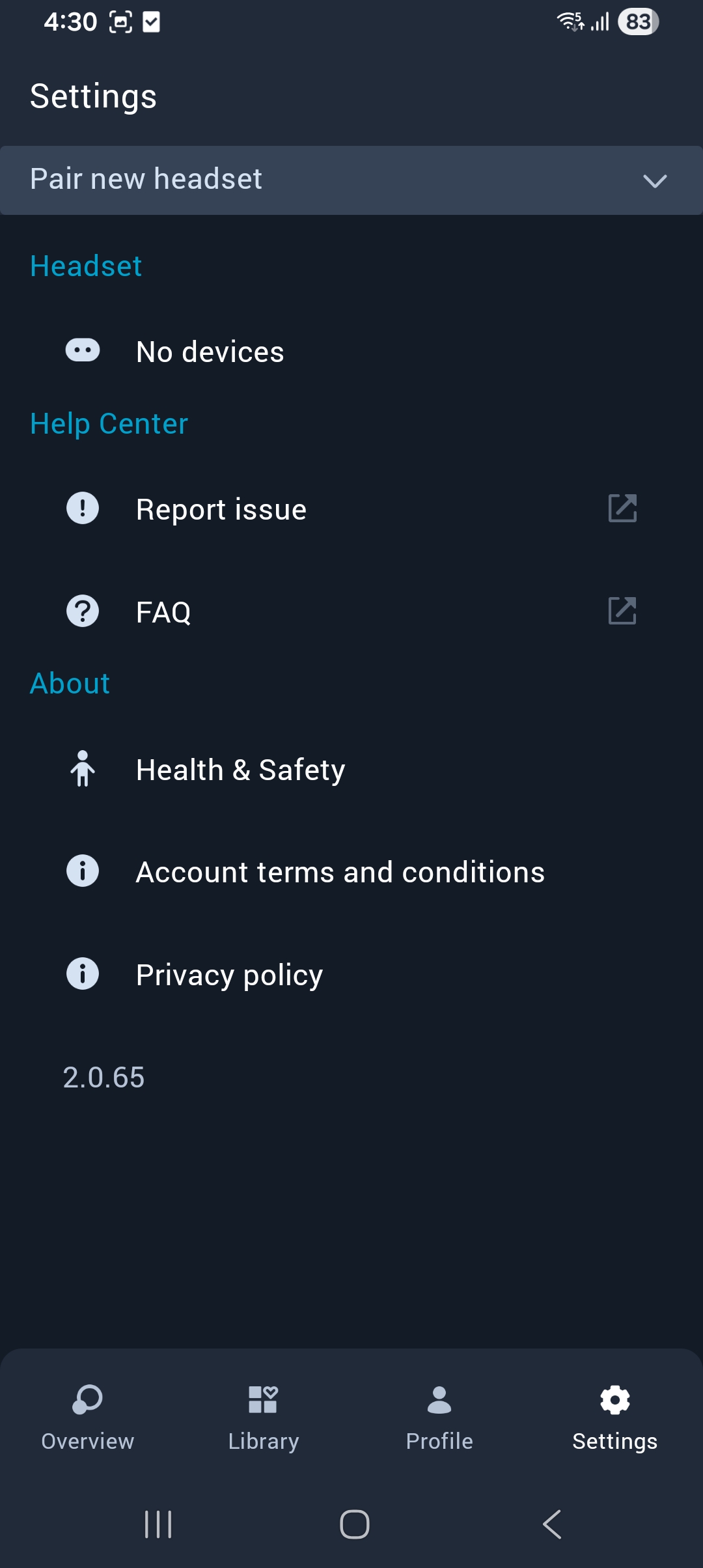
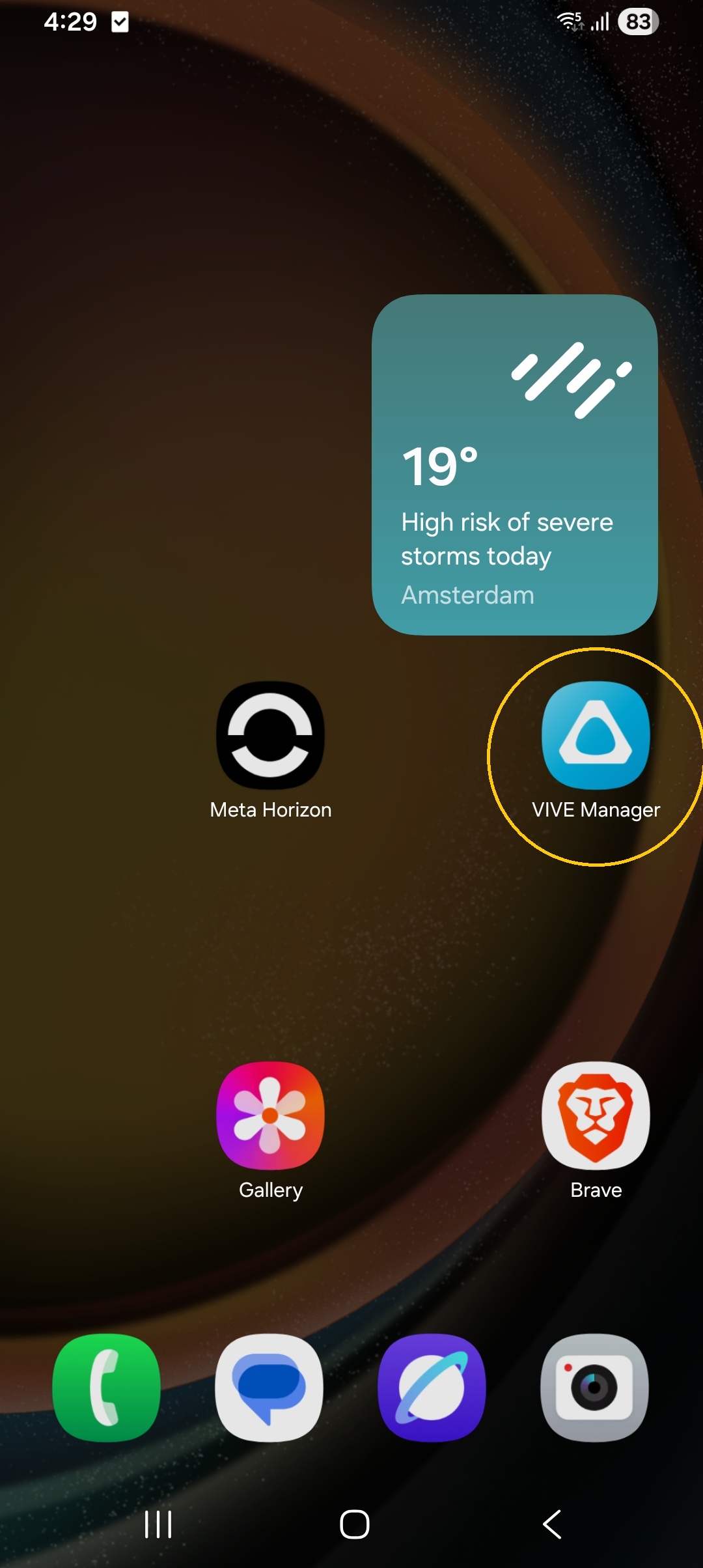
Select the Vive Manager app on the phone and navigate to Settings.
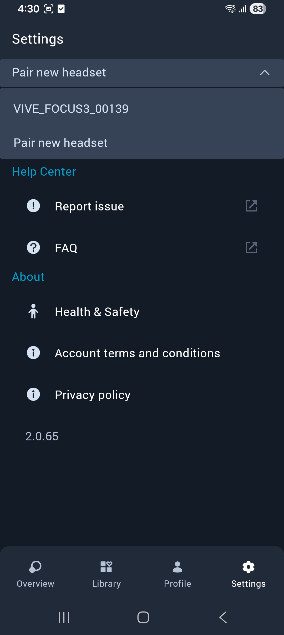
At the button Pair new headset, select the Golden HMD. This should be the only VIVE_FOCUS available in the list.
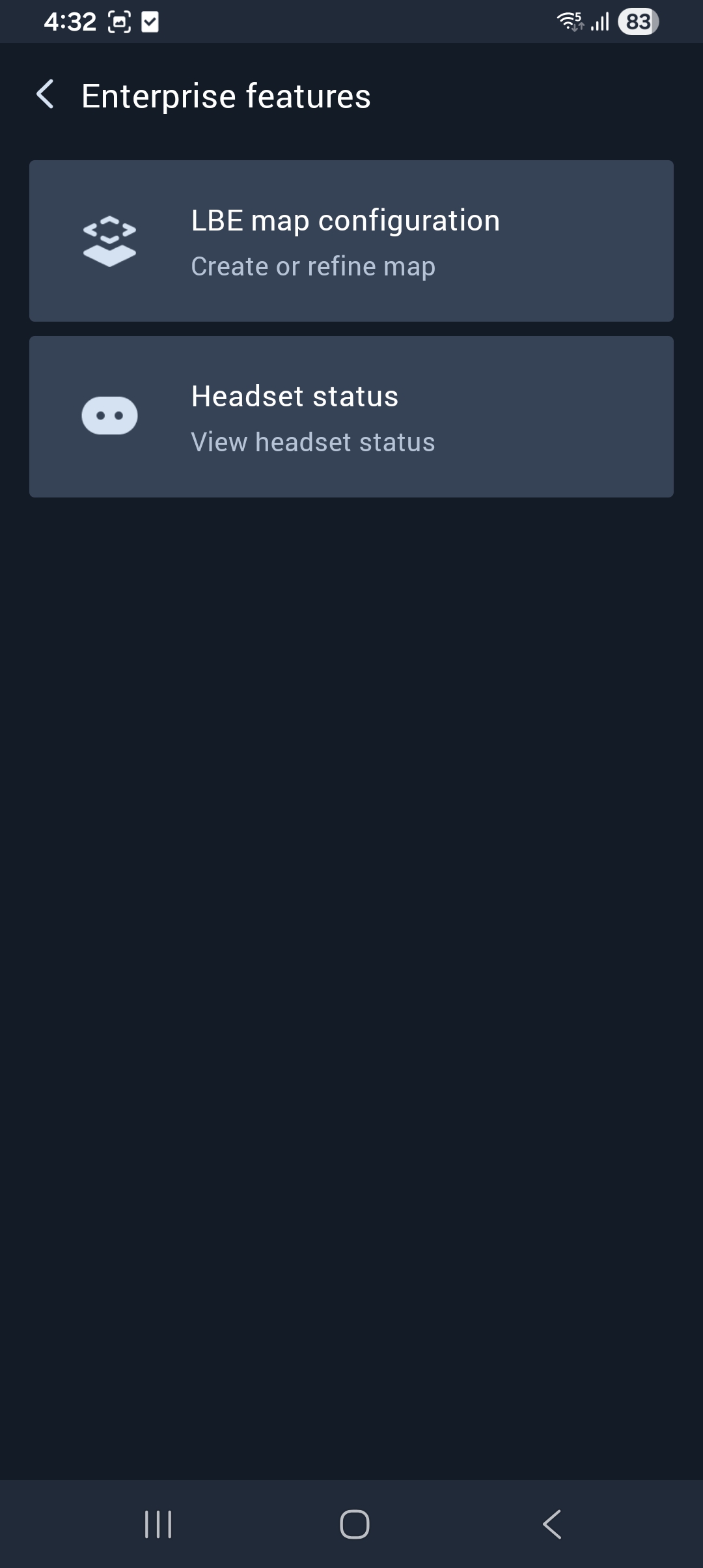
- Select Enterprise features
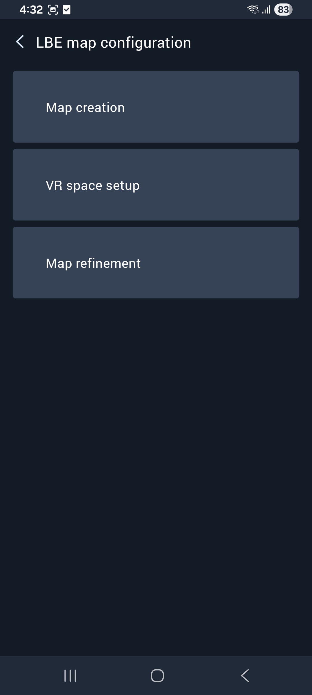
Select LBE map configuration
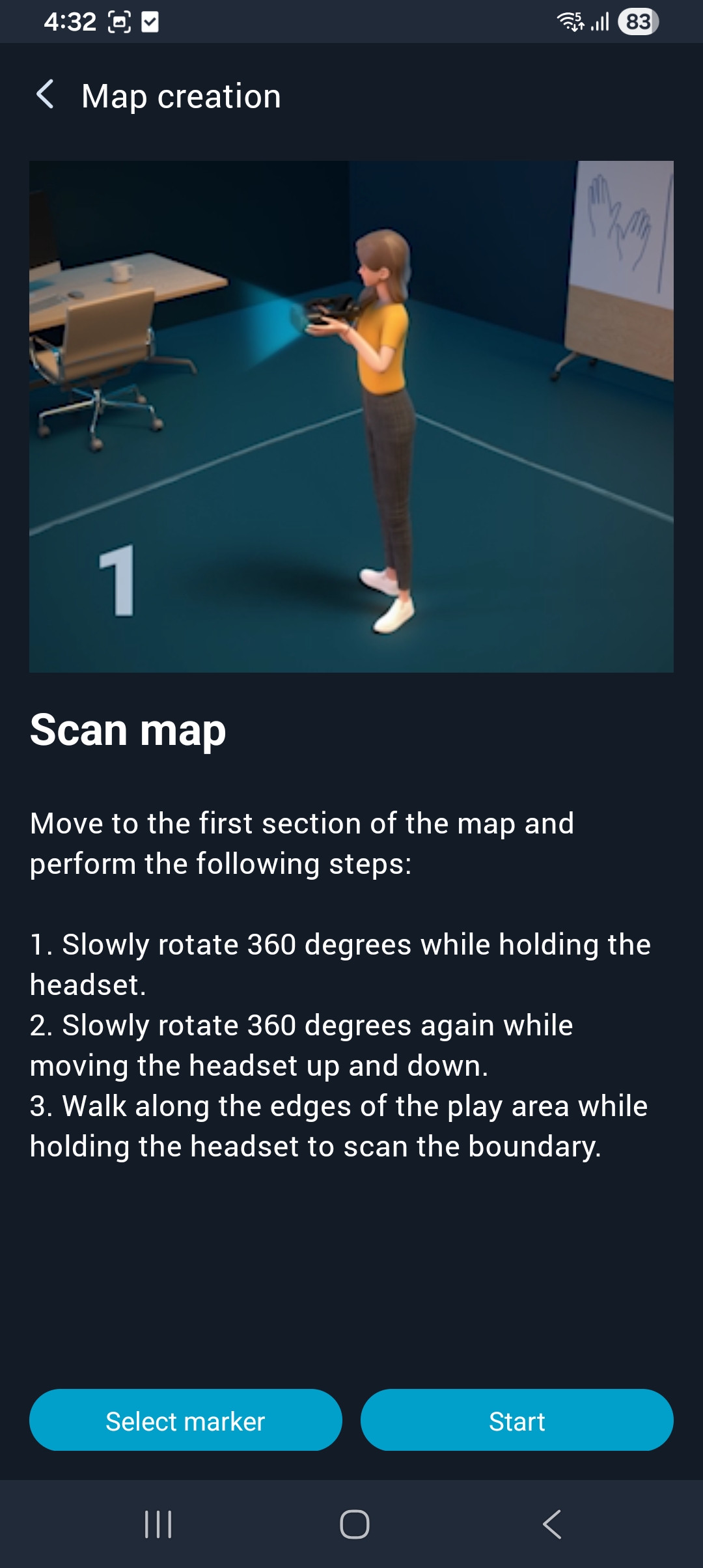
Select Map creation
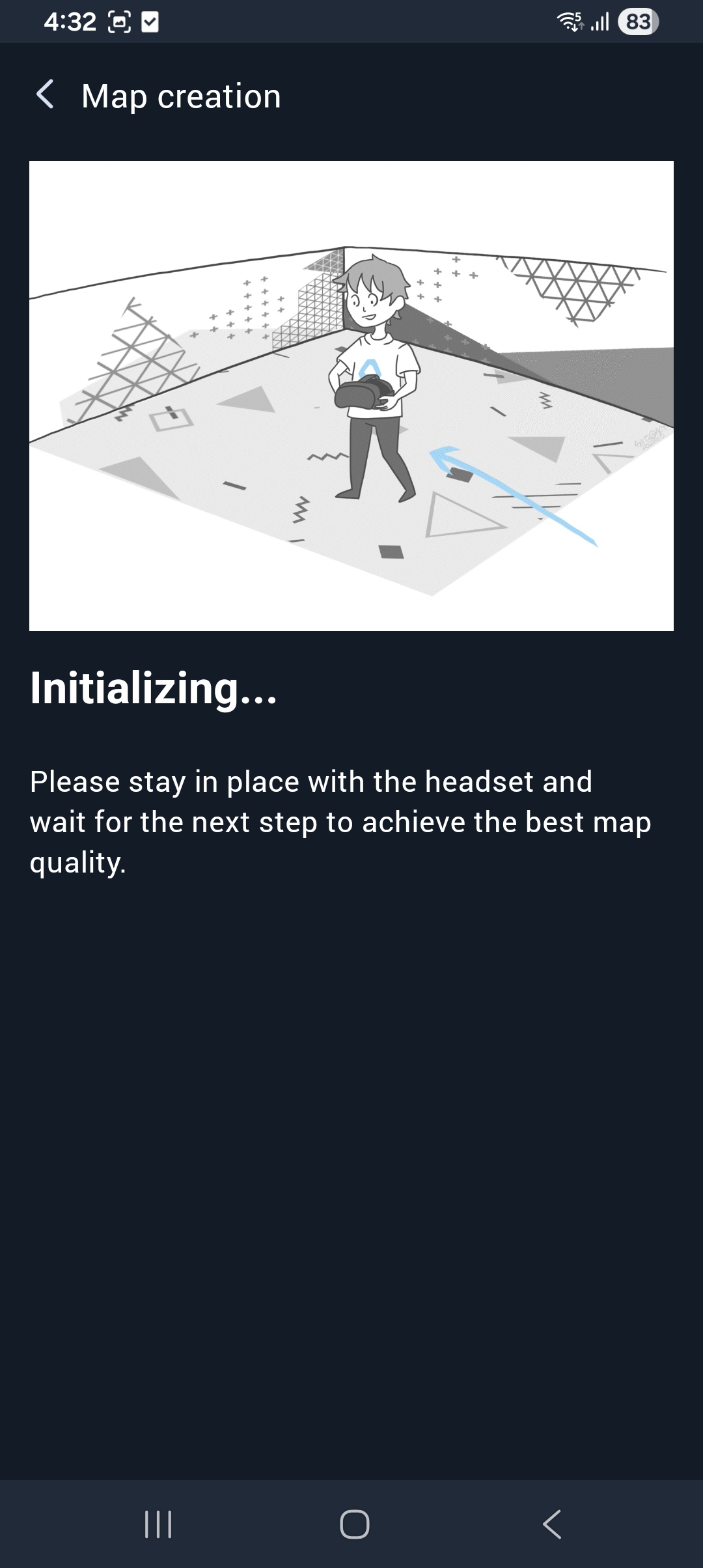
Stand in the middle of one of the outer segments and follow the instructions of the Vive manager.
WARNING
Follow the instructions of the application for the map scanning movements and take care to use slow and smooth motions for scanning. Using fast motions will result in a poor map.
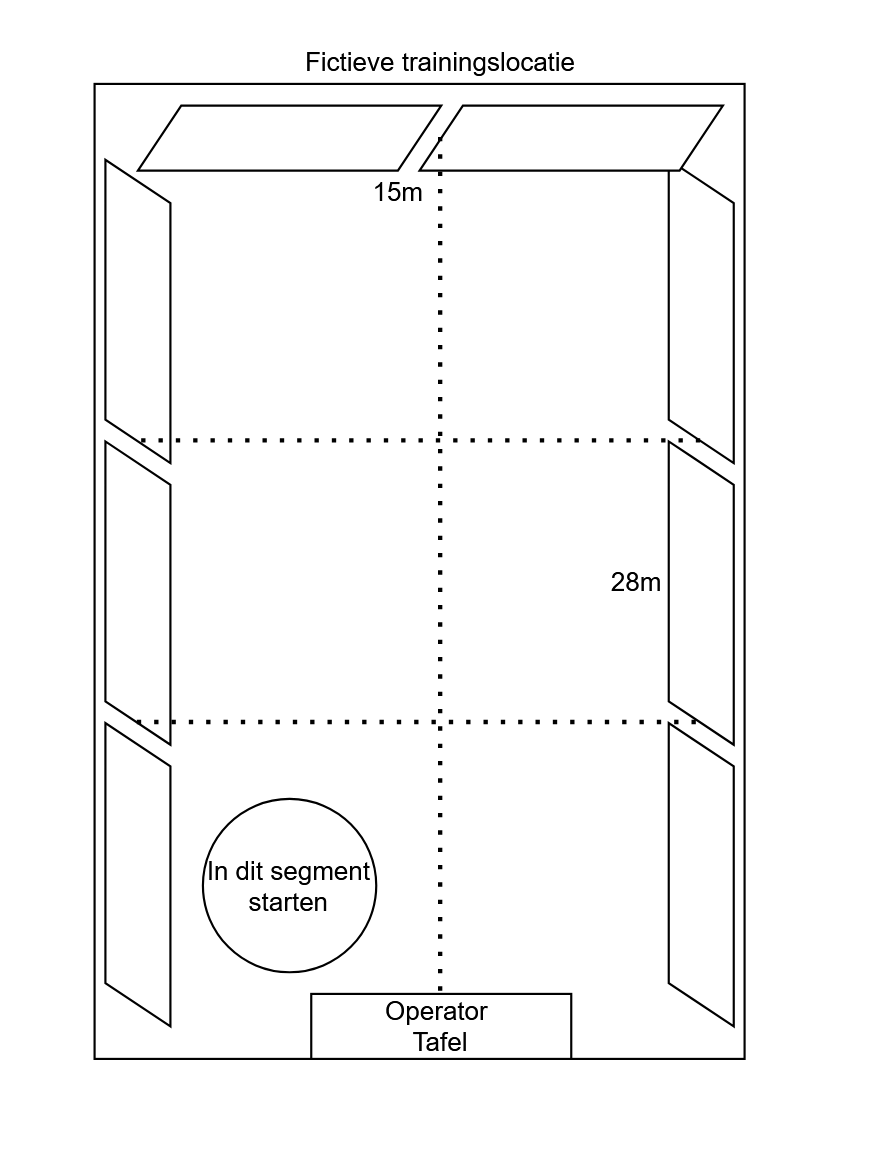
Devide the play area into segments by drawing an imaginary line between all the banners.
PAY ATTENTION
1) Use a maximum of 9 segments for a 30×30 area. 2) Every segment has to be square 3) Each segment must adjoin the previously scanned segment.
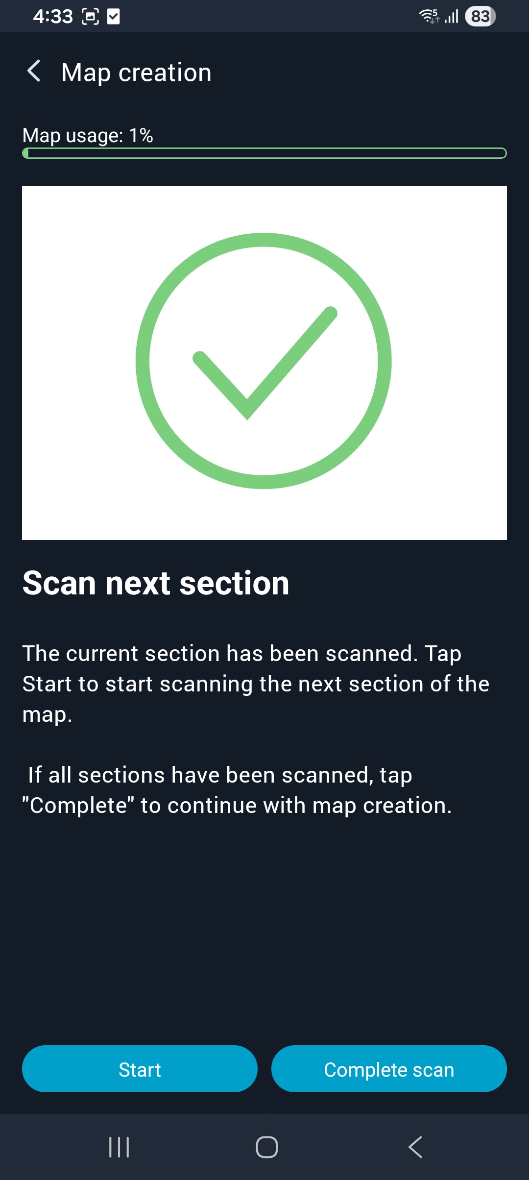
Scan all the segments needed for the play area and keep on scanning until the Vive manager tells you to move to the next section.
Be sure to finish the entire movement every section
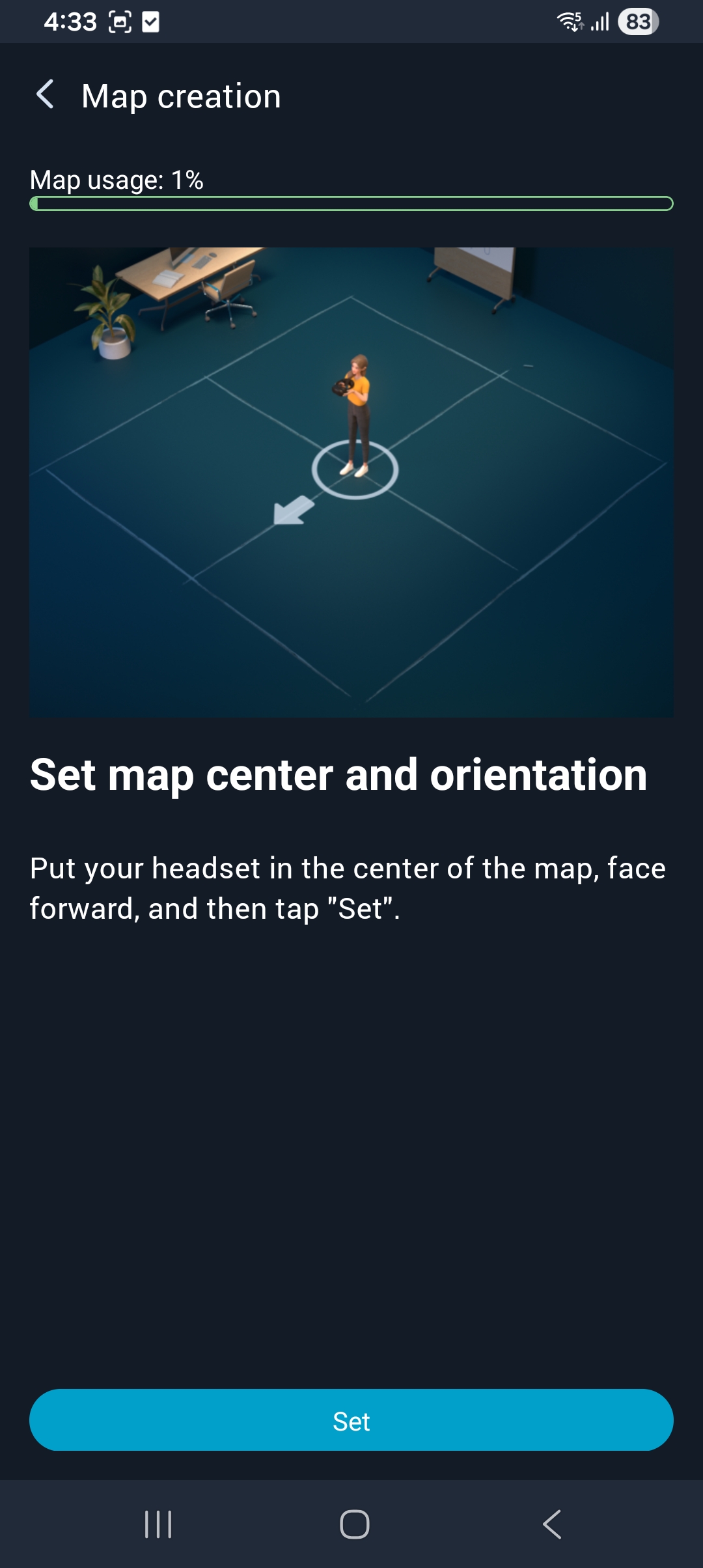
Press the button Complete scan when all segments have been scanned. Place the Golden HMD on the ground in the exact middle of the scanned map and press SET in the application.
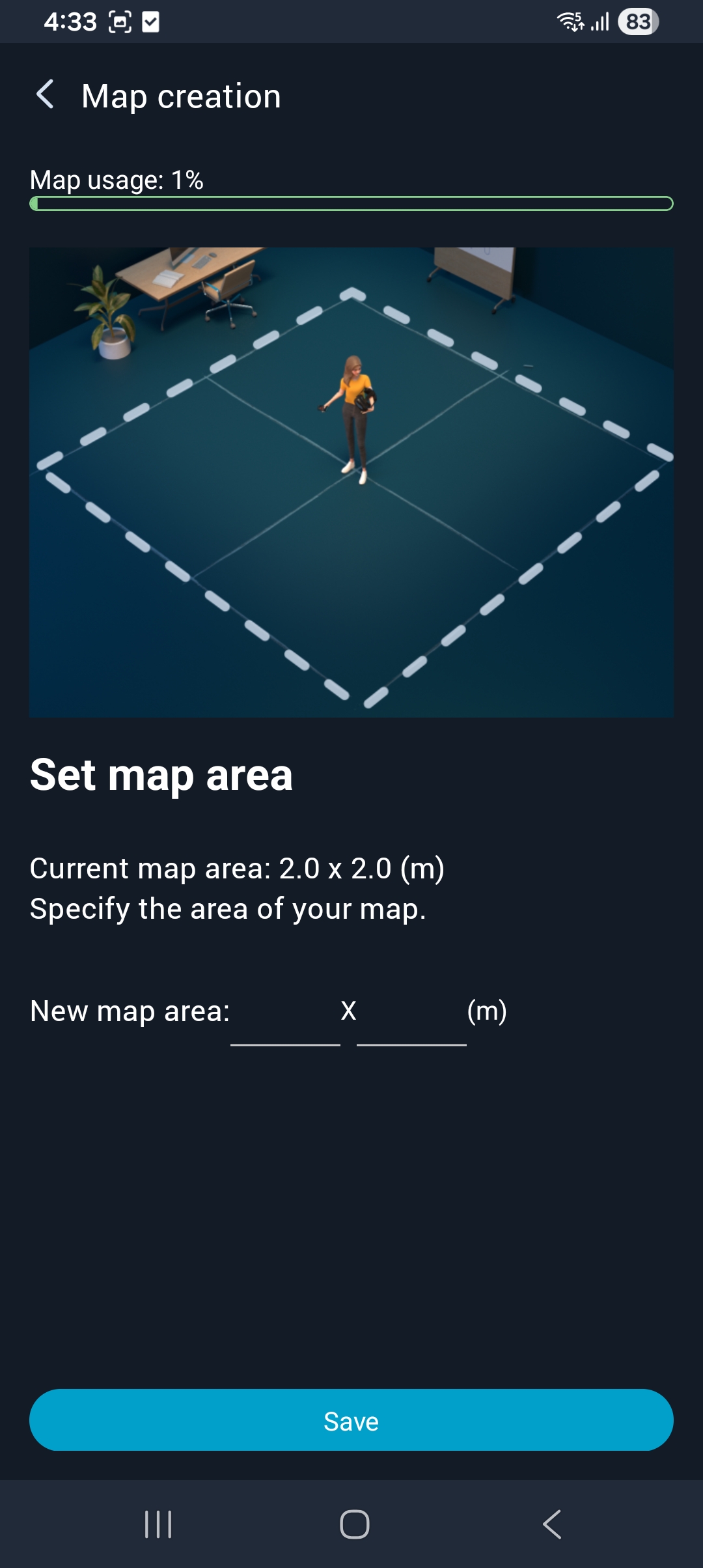
Add the dimensions of the field to the Vive manager application and press SET.
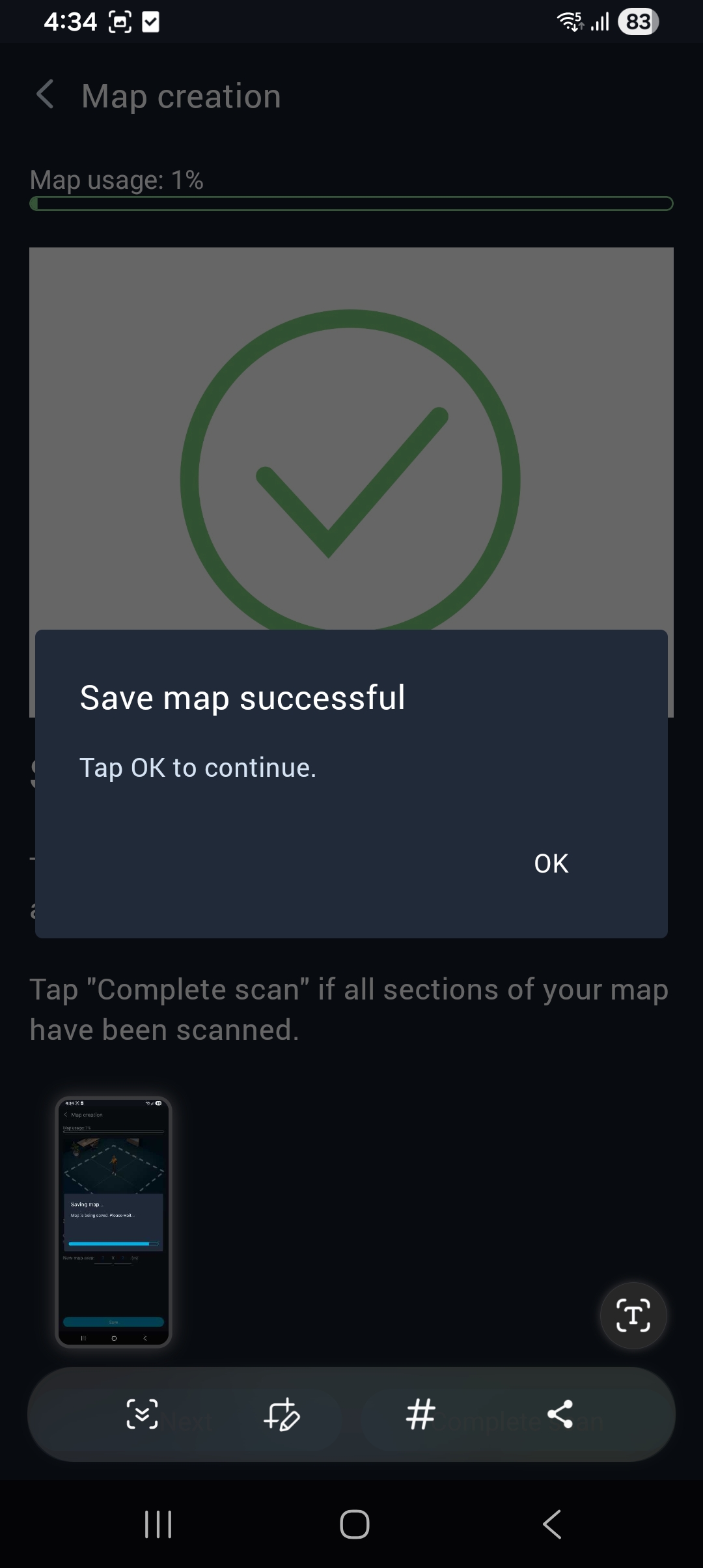
- Press Save to save the map.
- Verify if the map is correct by walking around the field while wearing the Golden HMD
Loading map to Smarvest HMDs
Necessities
CASE 01 | EXCON
CASE 05 | Positioning B
-> Smartphone
-> Golden HMD
-> Access points
CASE 06 – 11 | Smartvests
- Open the VBPConsole application on the desktop of the EXCON. Click on Devices and select the Golden HMD.
- With the Golden HMD selected, click on Export and give the map a good and comprehensive name.
If the HMD is not visible in the Devices tab, connect the HMD via USB-C cable to the EXCON.
While still in the Devices tab, select the HMDs that need the map and click on Clear map.
Press +Import and select the correct map under the tab Map name.
Check all the devices that need to receive the newly scanned map and press Import.
If the HMD is not visible in the Devices tab, connect the HMD via USB-C cable to the EXCON.
WARNING
Leave the "Batch configuration" field empty at all times.
System shutdown
If the system will not be used for training immediately after set-up – and will therefore remain unattended for a while – the system must be switched off. Also before the training field is to be dismantled, the entire system must be switched off.
System shutdown
On the EXCON on the SUIT home screen, click on Shut Down All and click Yes to turn off all Smartvests and the Spectator. If Delete user data is checked, all data under Start training → 1. Users will be deleted.
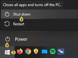
Close the EXCON by clicking Power (2)(3) in the Windows Start menu (1). Wait for the computer to shut down completely.
Press the red ON/OFF switch on the back of the EXCON to O.
Disconnect the external hard drive from the EXCON (1). Place this together with the accompanying USB cable back in the top drawer of the EXCON (2) and then close the drawer (3).
PAY ATTENTION
Confidential training recordings (AAR) must be removed from the external hard drive before the system is decommissioned. If the images cannot be deleted yet – because the training will be resumed at a later time – make sure that the external hard drive is kept in a safe place between training sessions.
Press the red ON/OFF switch on the back of the battery charger to O.
Verify that the Spectator is shut down and, if necessary, close it by clicking Shut down (2)(3) in the Windows Start menu (1). Wait for the computer to shut down completely.
Verify that the Spectator’s projector is turned off and turn it off if necessary by pressing the ON/OFF button on the top of the projector.
Verify that the speakers of the Spectator are switched off and switch them off if necessary by pressing the ON/OFF button behind the projector (1).
Press the red ON/OFF switch on the back of the Spectator to O.
Remove the plugs of both cable reels from the socket.
Leaving the system unattended
If the system has to be left temporarily unattended, keep the following points in mind:
System shutdown
If the system is left unattended, the system should be turned off. This is to prevent possible damage from lightning strikes or power surges. Shut down the system according to the instructions in System shutdown.
Storage replicas
If the system is left unattended, the replicas should be stored in a closed storage space.
Make sure the replicas are turned off and turn them off if necessary by pressing and holding the ON/OFF button for 2 seconds until all LEDs are off.
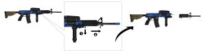
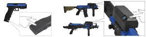
If not already done, remove the barrel from the Colt-C7 replicas. Pull out the lock knob (1) and slide the barrel off the replica Colt-C7 (2).
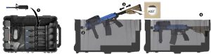
Place the barrel at the bottom of the box (1). Place the replica Colt-C7 in the case by inserting the pin of the replica into the hole on the side of the charging cables (2). Slide the sliding flask of the replica until the word KIST becomes visible in the circle on top of the sliding flask (3). The replica Colt-C7 now fits exactly in the box (4).

If connected, disconnect the replicas from the charging cables.
Disconnect the power cables of the replica boxes from the power cables of the replicas.
Close the steel drawer in the lid (1) and place the insert over the replicas (2). Close the replica chest.
Store the replica chests in a lockable room.
Hanging out Smartvests
Leave the Smartvests hanging from the hanging rack until the next training begins.
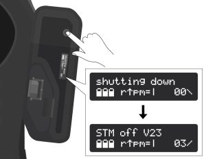
Verify that all Smartvests are turned off and turn them off if necessary: press and hold the Smartvest ON/OFF button until the display shows Shutting Down.
WARNING
Wait for the System off message before proceeding to the next step.
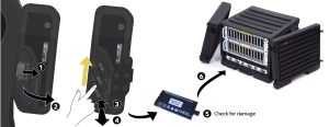
Take the batteries out of the Smartvests from bottom to top: Slide the latch to the side (1) to open the battery compartment cover (2). Press the battery to eject it (3). The battery can then be removed manually (4). Check the battery for damage (5) and place it – only if it is not damaged – in the battery charger (6).
WARNING
If batteries have been dropped or damaged, report this to the supplier. These batteries should NOT be used anymore.
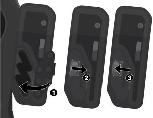
Close the battery compartment cover (1). Slide the latch to the side to fully close the cover (2). Release the latch and make sure the tab of the latch engages the slot (3).
Make sure that the Smartvests hang correctly on the Smartvest hanging rack. The Smartvest hangs with the hanging loop on the single hook on the back of the hanging rack and the headset hangs, on the headband, on the double hooks on the front of the hanging rack.
PAY ATTENTION
Make sure that: all cables hang freely, the three buckles on the front of the vest are closed, all Velcro parts are closed, the legs hang neatly apart from each other, the forearms at the front of the Smartvest are connected to each other with the Velcro strap of the forearm sensor.
Taking down the system
Take down order
- Make sure the EXCON is taken down last. All documentation is located on the EXCON.
Parts control
- Check all parts for damage before placing them back in the correct box. Damage to parts must always be reported to the supplier.
- Verify with the help of the inventory list whether all parts are back in the correct box.
Cables
- To disconnect the cables, press Push above the connector and pull the plug – not the cable! – carefully disconnect the cable. Then place the protective caps on both the sockets and the connectors of the cables.
- Roll up the cables neatly, without the cable twisting or getting tangled (see video below), and tie them together with the Velcro.
CAUTION
Do not roll the cables over your elbow. This causes twisting in the cable and can cause damage to the cable.
System shutdown
Shut down the system according to the instructions in System Shutdown.
Taking down the Spectator
Necessities
CASE 02 | Spectator
CASE 05 | Positioning system B
Disconnect the headset from the USB port under the monitor of the spectator (1) and place it back in the EXCON box (2).
Disconnect the network cable between the Spectator and the EXCON by pressing push and carefully on the plug – not on the cable! – to pull. Replace the protective caps on the connections on the EXCON and the spectator and on the connectors of the cable. Roll up the network cable and place it back in box 6 (cabling).
Disconnect the Spectator power cable extension – between the spectator power cable and the cable reel. Roll up the extension cord and place it back in box 6 (cable).
Slide the monitor – with the screen down and cable bundle at the front – into the bottom drawer of the Spectator. Roll up the spectator’s power cord and place it next to the monitor.
CAUTION
Be careful not to pinch the power cable.
Place the controller back in the holder.
Place the protective cap on the lens of the projector(1) and slide the projector into the box (2). Place both lids on the Spectator.
Close the projection screen.
Push the adjusting clamp up (1), slide the projection screen all the way down (2) and fasten it again by pushing the adjusting clamp down.
Press the button under the screen (1) and slide the legs up (2) so that they fold up (3).
Press the button (1) to fold and lock the tripod (2). Then place the tripod back in box 5 (Positioning System B).
Taking down the training field
Necessities
CASE 26 – 29 | Banner and tripods
Take down all the banners and tripods and put them back in their respective cases.
Taking down the Smartvests
Necessities
CASE 03 | Smartvest hanging racks
CASE 06 – 11 | Smartvests
Verify that all Smartvests are turned off and turn them off if necessary: press and hold the Smartvest ON/OFF button until the display shows Shutting Down.
WARNING
Wait for the System off message before proceeding to the next step.
Take the batteries out of the Smartvests from bottom to top: Slide the latch to the side (1) to open the battery compartment cover (2). Press the battery to eject it (3). The battery can then be removed manually (4). Check the battery for damage (5) and place it – only if it is not damaged – in the battery charger (6).
WARNING
If batteries have been dropped or damaged, report this to the supplier. These batteries should NOT be used anymore.
Close the battery compartment cover (1). Slide the latch to the side to fully close the cover (2). Release the latch and make sure the tab of the latch engages the slot (3).
Perform hygienic maintenance:
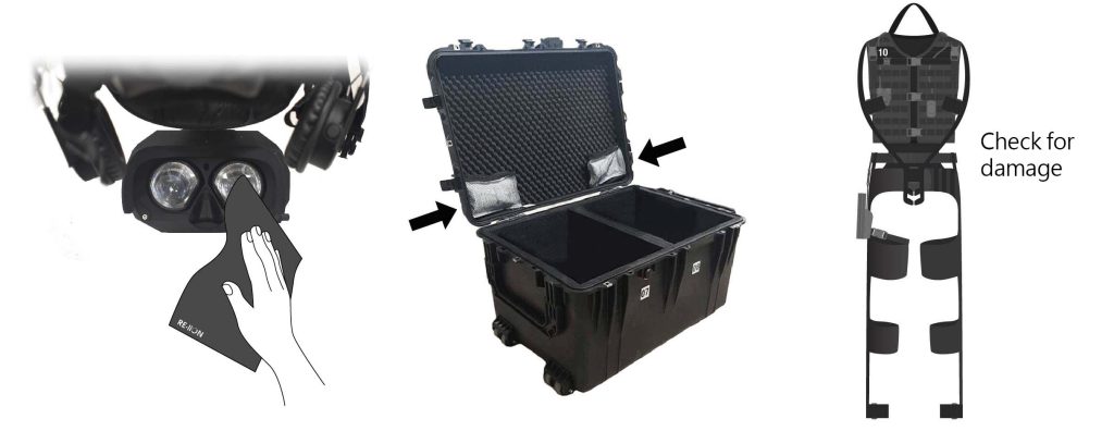
- Check the HMD and, if necessary, clean the lenses with the lens wipes provided.
- Check that the drying bags in the Smartvest cases are filled and replace them if necessary (replace them at least every 6 to 8 weeks).
- Check the Smartvests for damaged or worn parts. If parts are damaged or worn they should be replaced. Please contact the supplier for this purpose.
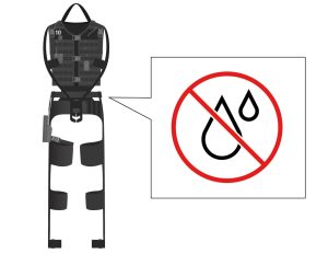
Check that the Smartvests are dry. The Smartvests must be completely dry before placing them in the case.
Make sure that the Smartvests hang correctly on the Smartvest hanging rack. The Smartvest hangs with the hanging loop on the single hook on the back of the hanging rack and the headset hangs, on the headband, on the double hooks on the front of the hanging rack.
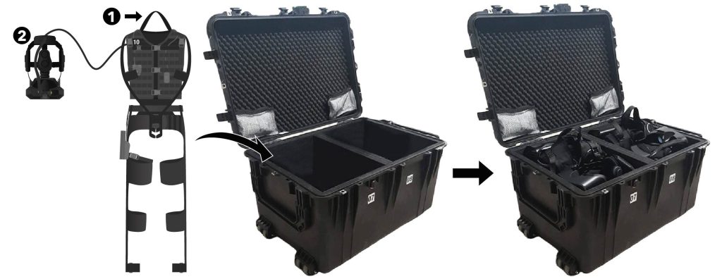
Place the Smartvests in the Smartvest cases: two Smartvests per case, one Smartvest in each compartment. Take the Smartvest with corresponding HMD off the hook. First place the backpack box upright against the back of the case and place the textile in front of it on the bottom (1). Then place the headset, upside down, on top of the textile (2).
Fully slide in the stands of the hanging rack.
Remove the hanging rack with hooks from the stands and pull up the locking knob (1) to separate the combined parts of the hanging rack (2).
Loosen the stands’ red locking screw and fold the three legs. Then tighten the locking screw again.
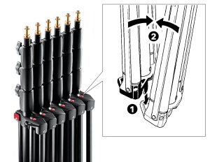
Place the tripods side by side (1) and snap them together (2). Place the tripods back in case 5 (positioning system B).
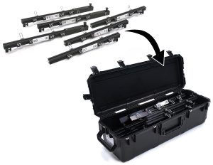
Place the hanging racks back in case 3 ( Smartvest hanging racks) and close the case lid.
Taking down replicas and chargers
Necessities
CASE 05 | Positioning B
CASE 12 – 15 | Replicas
CASE 16 | Battery charger
CASE 17 – 18 | Battery transport
CASE 19 | HMD charger and batteries
Remove the batteries from the battery chargers and place them in the battery transport case.
Disconnect the battery charger mains cable from the cable reel (1). Disconnect the cable reel from the power outlet (2), roll up completely (3) and place it back in case 6 (cabling).
Place both lids on the battery charger.
Make sure the replicas are turned off and turn them off if necessary by pressing and holding the ON/OFF button for 2 seconds until all LEDs are off.
If not already done, remove the barrel from the Colt-C7 replicas. Pull out the lock knob (1) and slide the barrel off the replica Colt-C7 (2).
Place the barrel at the bottom of the box (1). Place the replica Colt-C7 in the case by inserting the pin of the replica into the hole on the side of the charging cables (2). Slide the sliding flask of the replica until the word KIST becomes visible in the circle on top of the sliding flask (3). The replica Colt-C7 now fits exactly in the box (4).
If connected, disconnect the replicas from the charging cables.
Close the steel drawer in the lid (1) and place the insert over the replicas (2). Close the replica chest.
Taking down the EXCON
Necessities
CASE 01 | EXCON
CASE 06 | Cables
Disconnect the keyboard, mouse and headset from the USB ports under the monitor (1) and place them back into the top tray of the EXCON (2). Place the keyboard face down in the tray of the EXCON (3). Then close the tray of the EXCON (4).

Disconnect the EXCON’s mains cable from the cable reel (1). Disconnect the cable reel from the power outlet (2), roll up completely (3) and place it back in case 6 (cabling).
Slide the monitor – with the monitor face down and the AC power cable connector on the front – into the bottom tray of the EXCON. Roll up the power cable from the EXCON and place it on the left side next to the monitor. Place both covers on the case.
CAUTION
Be careful not to pinch the power cord.
Maintenance
PAY ATTENTION
Remove the batteries, before starting maintenance.
WARNING
Do not clean parts of SUIT with alcohol or chemical cleaners. Use clean water when cleaning. Cleaning agents are not provided.
WARNING
All maintenance not described here should be performed exclusively by personnel authorized by RE-liON.
Daily hygienic maintenance
Hygiene maintenance should be performed daily before and after training.
Smartvests
- Make a Mirazyne/Revivex solution using 1 ml Mirazyme/Revivex on 100 ml water
- Lightly spray the textiles of the suits with Mirazyme/Revivex after each session. Read caution below!
- Clean the screens of the HMDs before each session with the provided lens wipes.
- Clean the exterior of the HMDs with a slightly damp cloth.
- Clean the ear muffs every day with a slightly damp cloth.
- Inspect the smartvests for damaged or worn parts. If parts are damaged or worn they should be replaced. Please contact the local maintenance partner for this purpose.
- Check whether the drying bags in the lid of the Smartvest boxes are full. If they are saturated, contact the local maintenance partner to replace them.
CAUTION
If the electronics get wet they will damage irreparably, so mind the following points: 1. Spray only on the textiles, do not spray any cabling or electronics. 2. Spray sparingly. Too much will soak the textiles and will lead to solution leaking into the electronics. 3. Let the Smartvest properly dry before using or storing.
WARNING
After damp cleaning, wipe the component dry again immediately with a dry cloth and do not spray liquid on the devices. If liquid gets into the components, it may result in fire, electric shock or malfunction.
Other maintenance
The maintenance below can be performed if these parts have become dirty.
Cases
Clean and dry the outside of the cases with a dry cloth or brush.
If the cases are extremely dirty, they can also be cleaned with a wet cloth. In this case, make sure that all parts are removed from the case before cleaning it with a wet cloth. After cleaning, thoroughly dry both the outside and inside of the case before placing the parts back in the case.
WARNING
Keep the foam parts inside the cases dry.
Smartvests
Clean and dry the Smartvests with a dry cloth or brush.
If the Smartvests are extremely dirty, they can also be cleaned with a slightly damp cloth. Make sure the accessories are completely dry again before packing them.
WARNING
After damp cleaning, wipe the component dry again immediately with a dry cloth and do not spray liquid on the devices. If liquid gets into the components, it may result in fire, electric shock or malfunction.
Replicas
Clean the replicas with a dry cloth.
Tripods
Clean the tripods with a dry cloth or brush.
Cables
Clean the cables and connectors with a dry cloth and check that they are undamaged.
Preventive maintenance
Preventive maintenance is performed twice a year by RE-liON. The system will be checked on current and future wear and tear.